15kW Modular DC-DC Converter
Introduction
By the end of 2022, I felt stuck in a loop at university - that feeling when you want something new to happen in your life. I had plenty of theoretical knowledge but very little hands-on experience, which sadly is a common situation for students from Italian universities. I wanted a thesis that would bridge that gap, something that would actually let me build things, so despite still having about nine exams left (I know, not my brightest idea), I started looking for opportunities that could give me real engineering experience.

The final master thesis converter assembly
Getting the Opportunity
By chance, I came across a Telegram channel where BRUSA HyPower was sponsoring several thesis projects. It seemed like a great opportunity, so I sent in my resume, even though I didn't expect much of a reaction. Somehow I landed an interview, which made it clear how wide the gap was between academia and industry, I made it through with my self-esteem damaged but still in working condition.
There were many interesting topics to choose from, many of them software-related, and I was tempted. I’ve always been more naturally drawn to software, I started programming as a kid, writing plugins for my Minecraft server back on the hill where I grew up. Still, I chose a hardware-oriented thesis because I wanted to strengthen that side of my skill set.
The goal was to develop a DC-DC converter with a custom auxiliary SoftSwing circuit. This circuit is a Patented technology from BRUSA HyPower that ensures soft switching for all MOSFETs, practically eliminating switching losses in continuous conduction mode for a Boost/Buck converter. Continuous conduction mode is particularly desirable in these high power applications since it introduces smaller current harmonics in the input and output currents, reducing the size and cost of the required filters and ensuring easier compliance with electromagnetic compatibility (EMC) standards such as CISPR25.
These kinds of bidirectional Buck/Boost converters are often used in automotive applications, particularly for fuel cell systems. The converter steps up the fuel cell voltage (around ) to the high-voltage bus (around ), which is used to power the electric motor. That’s the converter I would be designing, building, and testing from scratch.
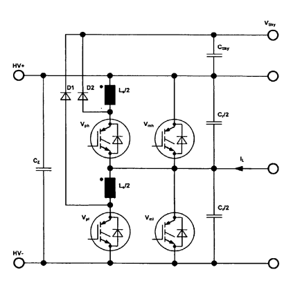
Detail of the SoftSwing© topology, as seen in the original IGBT-based converter shown in the US20100301831A1 patent
Moving to Switzerland
On the night of December 28th 2022, I packed everything and drove from Rome to Buchs, Switzerland, about . It was a long drive through Italy and the Alps, and I was in a great mood with a good playlist. Looking back, though, crossing the San Bernardino Pass in the middle of winter on summer tires in a Volkswagen Golf was probably a Darwin-Award-level move.
It wasn’t until the next morning that it truly hit me where I had landed. The Rheintal mountains looked like they were about to fall on me, and everyone around me was speaking a language I could barely recognize. For the first time in my life I showed up to work, received some comments about being overdressed for the work environment, then started to work.
The Concept
For the first few weeks I studied the operating principle of the converter and I made some concepts of how the hardware would like in my naive university-student mind. The idea was to make the hardware modular, in order to maximize reusability of the components for future projects and to be able to quickly swap something out (like the main choke) to try a different configuration if needed.
Of course, when making something modular there is always the topic of choosing what a module is, which is not as trivial as it sounds. Is it the half bridge, is it the MOSFET and gate driver assembly, is it the gate driver? I chose the modules somewhat arbitrarily at the time, and the concept is shown below.
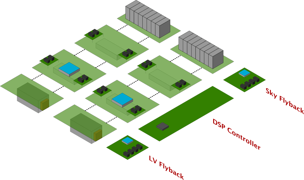
Modular DC-DC Converter Concept
The idea was to have some shared control and auxiliary supply modules, and then to have power-cell modules that could work in parallel to potentially increase the output power.
Now, if you're a power electronics engineer you are probably wondering "Ok but how can this even work? What about the common mode noise across all the boards? What about the incredibly large gate loops for the power cell?" and you'd be right. Due to my lack of experience as a soon-to-graduate Mechatronics Engineering student, I didn't consider these things. But as I will show later the technology that was used made all of these problems almost negligible.
Hardware Development
The hardware design phase began with the schematic capture in Altium Designer, where I laid out the entire system, from the main power cell and the auxiliary SoftSwing circuit to all the low-voltage subsystems such as LDO regulators, Sallen-Key filters, isolated power supplies for the gate drivers, and the gate-driver circuits themselves. This stage was less about simply “drawing connections” and more about understanding the converter as a living ecosystem, where every functional block subtly interacts with the others, which quickly showed how far classroom theory can be from the messy reality of hardware design.
Once the schematics started to take shape, I moved on to the PCB layout, which proved to be a humbling exercise in iteration. I restarted the design process twice, partly out of frustration and partly because I realized that my first attempts lacked the spatial hierarchy and current-path awareness needed for a design operating in the tens of kilowatts. The second iteration introduced a clearer separation between the POW (power) and SYS (control) domains, a structure that’s more in line with industrial practice and far easier to debug or repurpose later.
Unfortunately, I can't share the full schematics or the complete layout here, but below is the only board that by the end of the thesis I felt somewhat proud of, the gate driver board.
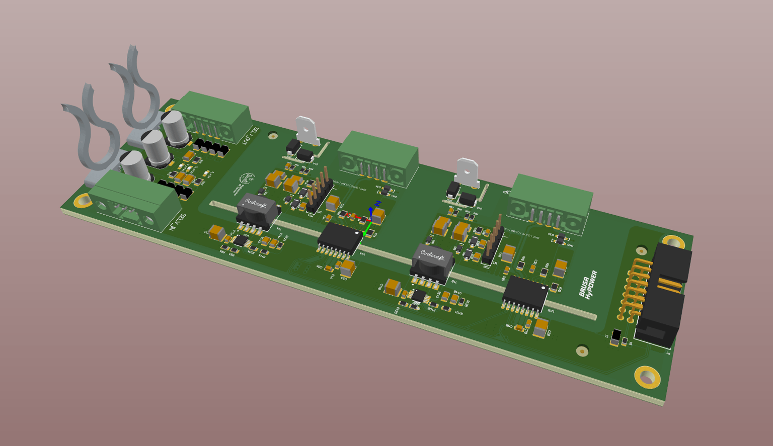
Detail of the Gate Driver module as shown in the Altium 3D viewer
Looking back at it now, there are plenty of things I would change. I would eliminate the electrolytic capacitors to improve long-term reliability, shrink the switching loops by rethinking the connector placement, and choose different components with cost optimization in mind. For example I would replace the UCC21717-Q1 gate-driver IC from Texas Instruments, which is like the Ferrari of gate drivers, priced at around per piece.
Still, the design was a valuable learning experience. One of the most important things that I learned was that designing the hardware of a full power converter in 2-3 months with little to no experience is a very stressful endeavor. These things benefit from a little more thought and refinement, but it ended up working anyway.
Software Development
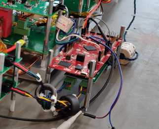
The control software was developed in C and deployed on a Texas Instruments C28004 Piccolo DSP, using Code Composer Studio as the development environment. Achieving real-time SoftSwing control demanded fast computations, and the chosen DSP was up to the task for this project. In a full-scale automotive application, however, additional parallel tasks would likely require a more powerful DSP or even an FPGA. For the scope of this thesis, the C28004 handled closed-loop SoftSwing control across the entire output voltage range with reliable accuracy.
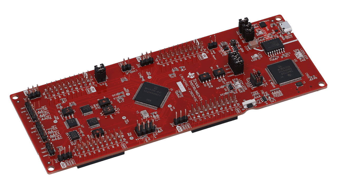
The board used for control development (Texas Instruments C280049 Piccolo DSP)
The implemented controller was relatively simple. A voltage controller loop regulated the output voltage by adjusting the duty cycle reference for the SoftSwing controller. The SoftSwing controller then generated the appropriate gate signals to achieve soft switching, based on real-time measurements of voltages and currents in the converter. No advanced control techniques were used basically due to time constraints - the hardware development had already eaten up a significant part of these six months, and this simple control loop proved to be good enough to demonstrate the concept.
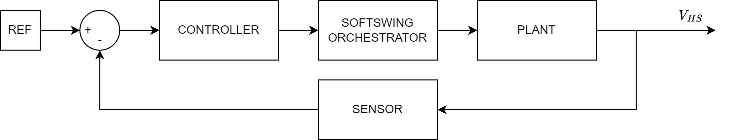
The simple voltage control loop implemented in the DSP
The most original part of the thesis was the implementation of the SoftSwing modulator, which required careful timing to ensure that all MOSFETs switched at zero voltage or zero current. This involved calculating the precise switching instants based on the measured inductor current and capacitor voltages, and adjusting the gate signals accordingly. In order to do this expensive and complex FPGAs were used in the past, but this thesis demonstrated that a relatively simple DSP could handle the task effectively.
One thing that I should definitely have implemented but didn't, was some form of software hard faults. The CMPSS peripherals allow for easy implementation of that, where you can just route a compare event to the EPWM peripheral to turn off all the MOSFETs in case of overcurrent or overvoltage. Guess I like to live dangerously.
Testing & Results
Once all the PCB boards arrived and I carefully soldered all the components, it was time for testing. The first step was to test each module individually to ensure they worked as expected. This involved checking the gate driver signals, verifying the SoftSwing operation, and ensuring that the control board could communicate with the power modules.
I was careful to the point of frustrating the people around me while testing the boards, but it turned out I was right to be cautious. I found several small mistakes that would have for sure resulted in blown components if I had just powered everything up without testing, like diodes that were too slow, control-related measurements that were highly affected by common mode noise or dead times that were too small.
The implemented fix for the common mode noise on the DSP measurements
One particularly interesting issue arose from the parasitic inductance between the main power cell and the DC link capacitors. During initial low-power, hard-switched operation, I observed strong ringing on the MOSFET transitions, the kind of oscillations that make you think "damn this is gonna blow up".
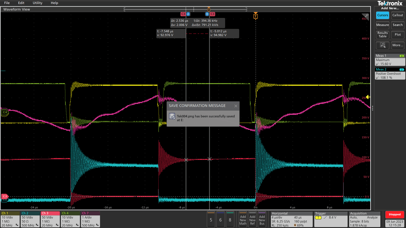
The ringing observed during initial open-loop tests
After some investigation, I discovered that the root cause was the physical separation between the switching nodes and the DC link capacitors. The inductance of those traces, although small in absolute terms, was enough to interact with the output capacitances of the MOSFETs and cause high-frequency oscillations. The solution was a good physical hacking exercise, I added a few small ceramic capacitors with very low parasitic inductance directly across the switches, effectively damping the resonance and stabilizing the transitions.
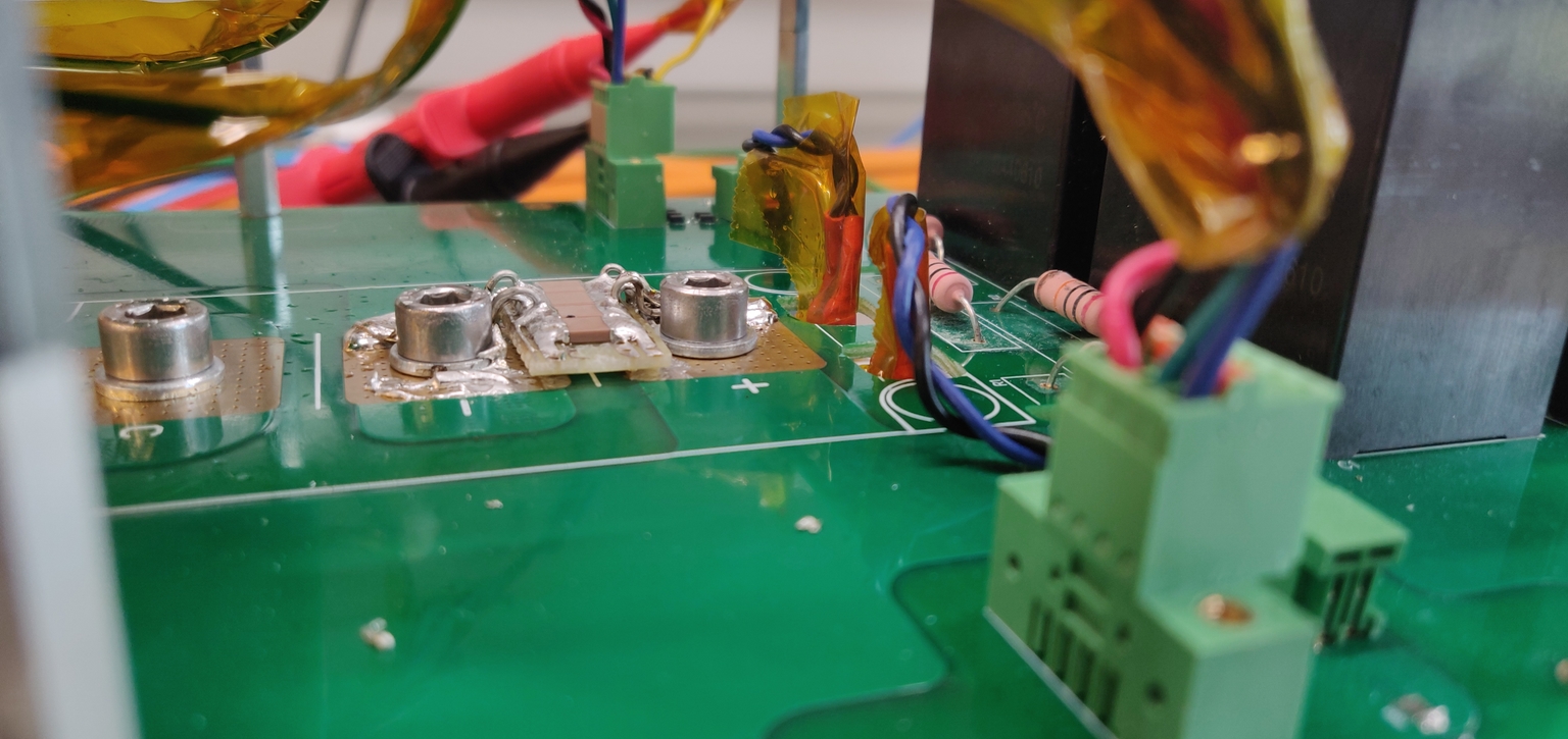
The fix for the ringing and overshoot issue: small low-inductance capacitors added near the switches
With the low-power tests complete and the hardware behaving properly, I gradually increased the output voltage up to and the output power to the rated . This phase required patience, as even a small mistake could have resulted in blown semiconductors and a premature funeral for my master thesis. Using the oscilloscope, I confirmed that all MOSFETs were switching either at zero voltage or zero current, validating the SoftSwing operation and confirming that the control logic was behaving as intended.
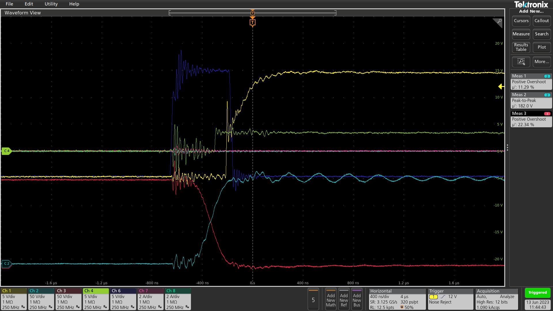
Detail of a MOSFET transition
Thanks to these soft-switching conditions, the converter achieved negligible switching losses, resulting in very good overall efficiency. The modular structure, which initially seemed risky due to longer current paths and higher parasitics, proved to be manageable. The SoftSwing operation effectively reduced the effect of the stray inductances that would have been problematic in a hard-switched converter, allowing the system to operate relatively smoothly even at full load.
Over the following days, I conducted efficiency measurements at various load points to characterize the converter’s performance across the operating range. The converter consistently achieved efficiencies above , with SoftSwing operation providing a clear advantage of around compared to hard-switching conditions.
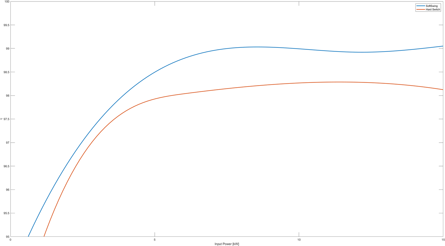
Interpolated efficiency curve of the converter
A keen eye will notice that the efficiency curve looks smoother than one would expect from real measurement data. That’s because the values were derived from the power supply readings, which turned out to have relatively high uncertainty. As a result, only the mean efficiency could be estimated reliably, while the standard deviation was too large to justify showing individual data points. The interpolated curve still provides a representative view of the converter’s behavior, and the observed efficiency gain from SoftSwing operation is unmistakable.
In the end, the converter delivered exactly what it was designed for: high efficiency, soft switching across the high power operating range, and modular flexibility. The project validated the feasibility of the SoftSwing topology for high-power DC-DC conversion and showed that, with the right approach, even a modular prototype driven by a simple and cheap DSP can perform well.
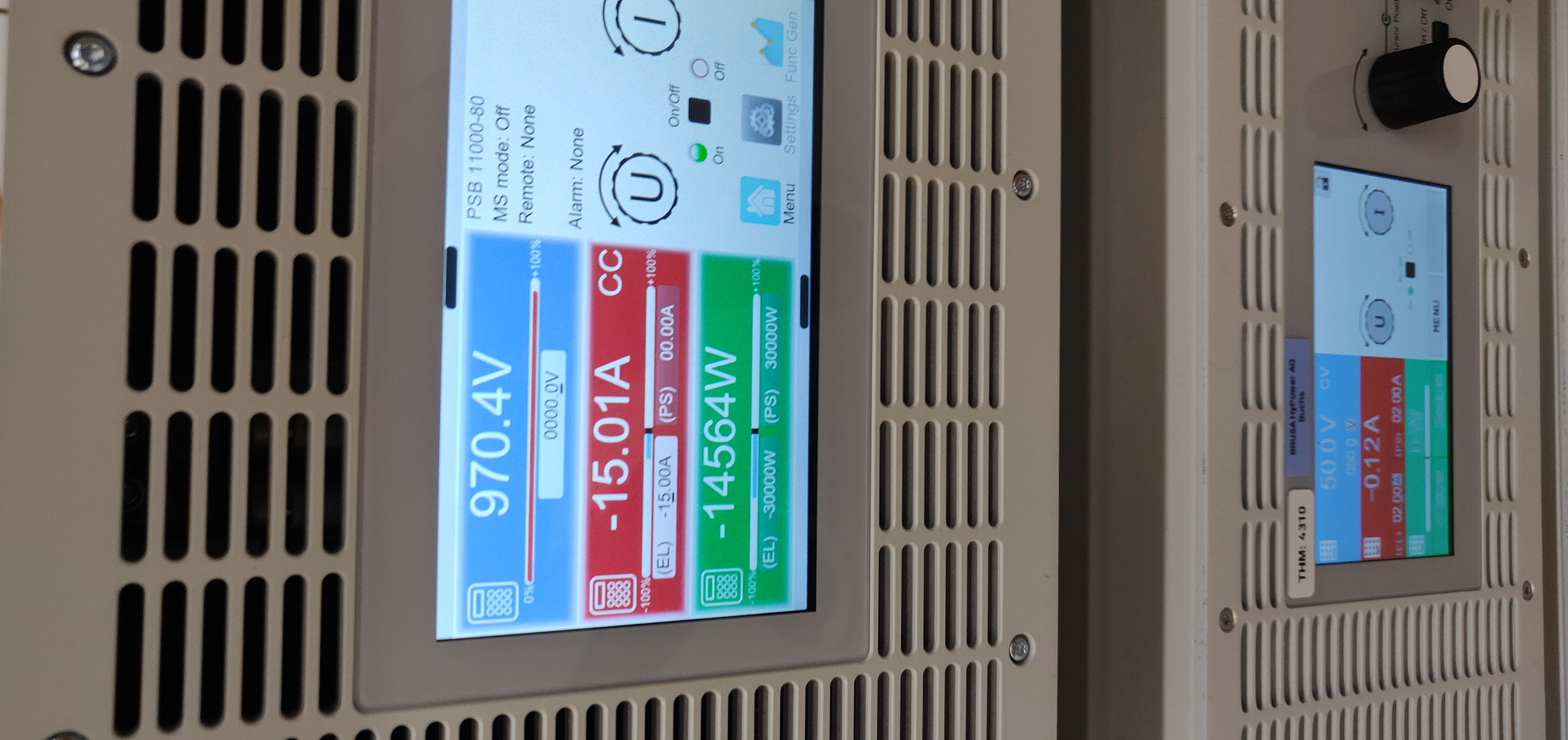
The power supply screen at maximum voltage and full load
All in all, it was a very interesting thesis project that taught me a lot about power electronics, hardware design, and real-world engineering challenges, despite probably knocking a couple years off from my life expectancy. Now that this problem was fixed, time to make up a new problem. Stability is overrated anyway.